Register To Comment
Page 3 of 22 FirstFirst 1234513 ... LastLast
Results 21 to 30 of 211

Thread: Liftoff (FW) build diary

  1. #21
    To bad, depends how you look at it. Those plastic push locks are strong enough for 10 bar.
    But then the hose needs to go in perfectly straight, without any sideway force or pull on it.

    At work we have problems in that respect. Packaging machines have in certain cases pistons that move along with the packaging material, even for meters.
    If it is done well, it takes years before any hose or push lock fails, and then it's most of the time the result of degradadion by heat or UV light.
    But some lazy people take a short cut when that happens. Not replacing the hose, but just cutting out the failed piece and by pulling and using up the slack reconnecting the 2 parts with a connector. And if that doesn't work, by rerouting the hose, not even bothering to see if it chafes or pulls at anything. Result. More problems.

  2. #22
    Guess you're right maddox, the elbow fittings from the QEV to the 5way valve are a bit stressed - think I'll replace them with threaded 90' fittings, should come shorter than the current set-up and the fittings will be better aligned.

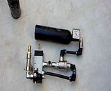
    Here is a clip(Hope it works!) of the LP system test. Didn't bother connecting the solenoid, the valve has a manual deploy button :wink:
    Looks like it's working ok, will have a better idea when the actuator is finished and tested


    Progress with the build of the chassis and motor housing is in good progress as well,

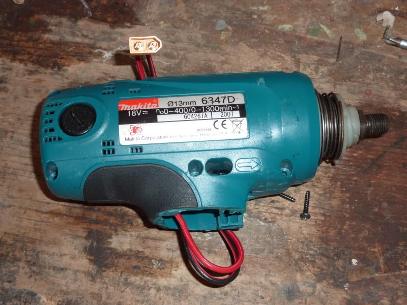
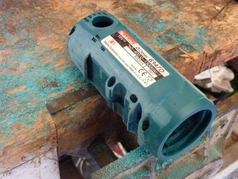
    Started off with these motors


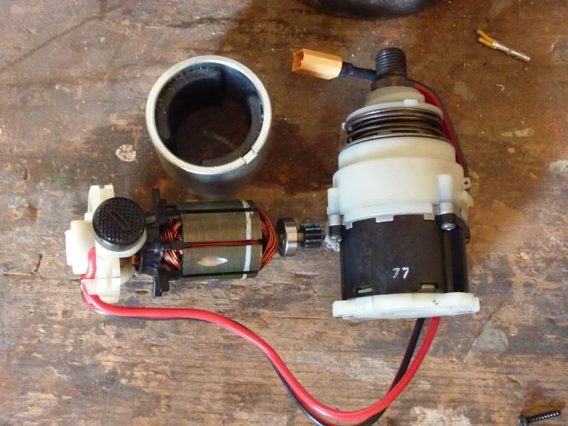
    Took them apart


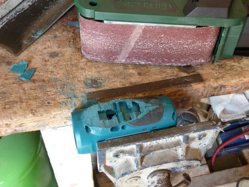
    And put them on a diet


    After some sweat and a good slimming treatment with the belt sander they look like this:


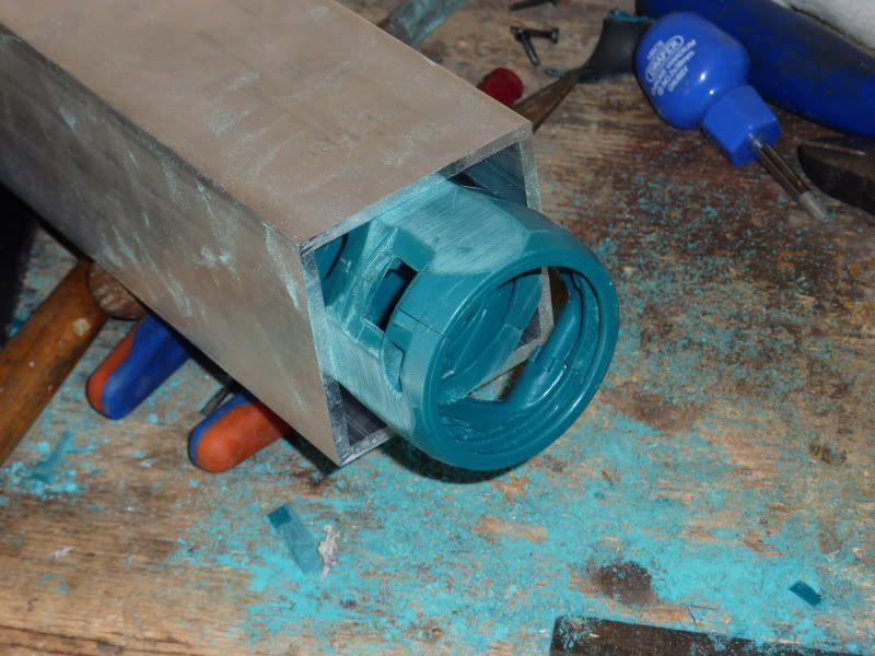
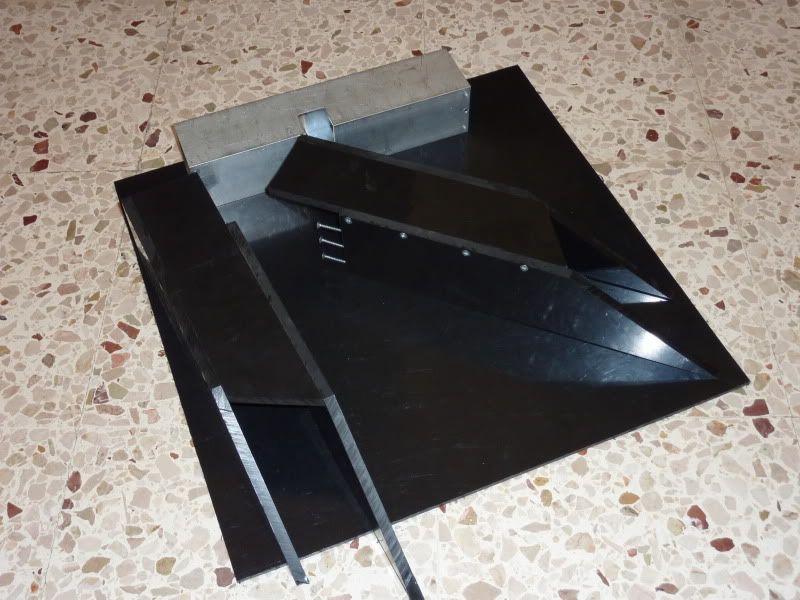
    Now the motors can fit into this... the motor housing/retainer


    Motor housing bolted on to baseplate


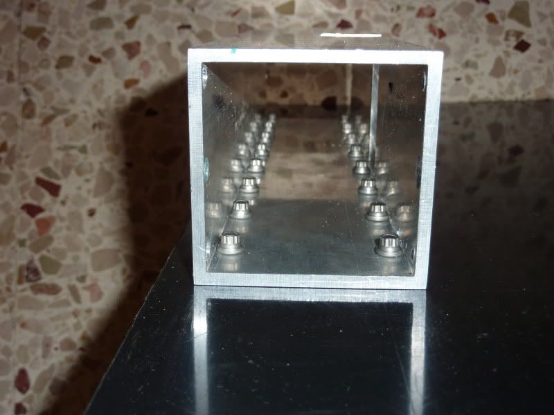
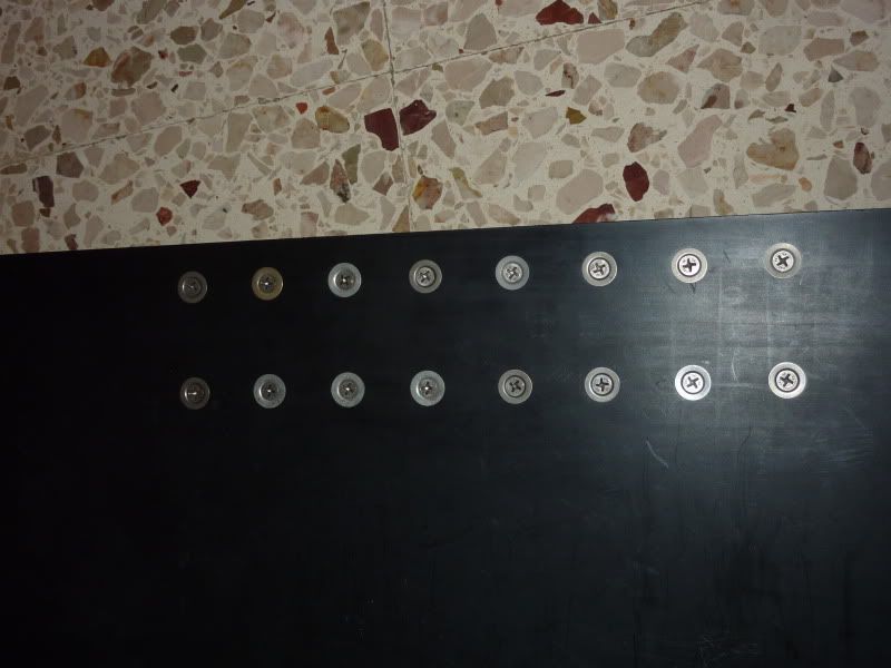
    bottom view of baseplate


    And these are the parts competed so far


    I'm happy with the progress so far, not much problems till now apart from HDPE being a bit difficult to work with till you get used to it. Hope that by next week I'll get the actuator and wheels, I want to see it moving

  3. #23
    That is a lot of rivnuts.

  4. #24
    ''That is a lot of rivnuts.'' well I had the team telling me the base was flimsy, my dad saying that normal wood screws will get pulled through the base - so I did something to prove them all wrong!
    To be honest all those screws are an overkill, but that's where most of the power is concentrated, the motors and the hinge point for the flipper arm...so better safe than sorry :wink:

  5. #25
    Very sensible, lots of fixings make a strong robot

  6. #26
    kane's Avatar
    Roboteer

    Quote Originally Posted by Liftoff
    Guess you're right maddox, the elbow fittings from the QEV to the 5way valve are a bit stressed - think I'll replace them with threaded 90' fittings, should come shorter than the current set-up and the fittings will be better aligned.
    Could always go for smaller tubing for the retract (buffer fill). That would allow for a tighter bend radius.
    Kane Aston
    http://www.makerobotics.com

    Co-owner and builder of BEHEMOTH

  7. #27
    That's true Kane - but I got no ''retract'' in this system, the tube which is out of alignment (the one from the 5 way valve to the QEV) is the main supply to the buffer tank. Retract will be by spring dampers or bungee chord.
    Its still a good option to use smaller tubing though, lets see how the actuator goes and then proceed from there - I only need to lift 17kg, and if my calculations are right, using a 63mm dia actuator at 10bar should get a force of 300kg, should be enough I hope might also consider lowering the pressure to conserve Co2 and get less stress on the whole bot...

  8. #28
    Looks really good. Don't forget your dump valve though.

  9. #29
    ''Don't forget your dump valve though'' Hmm...totally ignored that

    I could place one on the regulator inlet, but that will be difficult to operate from outside (as per FRA regs.).
    Having said that I probably wont need it as its not listed in these regulations where the competition will take place:
    http://ieeesbmalta.org/index.php?option ... mitstart=1

    Will try to think of how it could get incorporated into the system anyway - can someone please post a pic or link of a similar valve just to get an idea, thanks

  10. #30
    this looks really good so far!

    btw, you don't need large tubing on the buffer tank feed.

Register To Comment

Posting Permissions

  • You may not post new threads
  • You may not post replies
  • You may not post attachments
  • You may not edit your posts
  •