


Well, been working on the selfwrighter for 360 so thought id show a few pictures of it. thanks to Ed wallace for helping us out with the cnc work when his boss wasnt looking lol
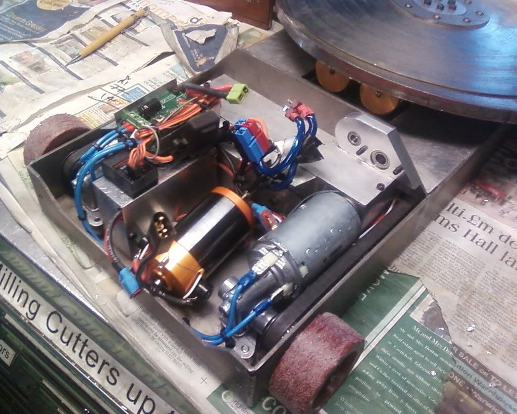
Firsto of, heres the space i had to cram everythin into, decided an astroflight 25 with a 450:1 gearbox should be able to do the job on 14.8v hopefully
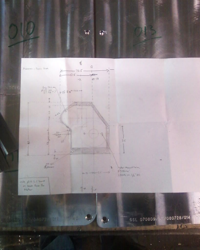
quick sketch of what's needed
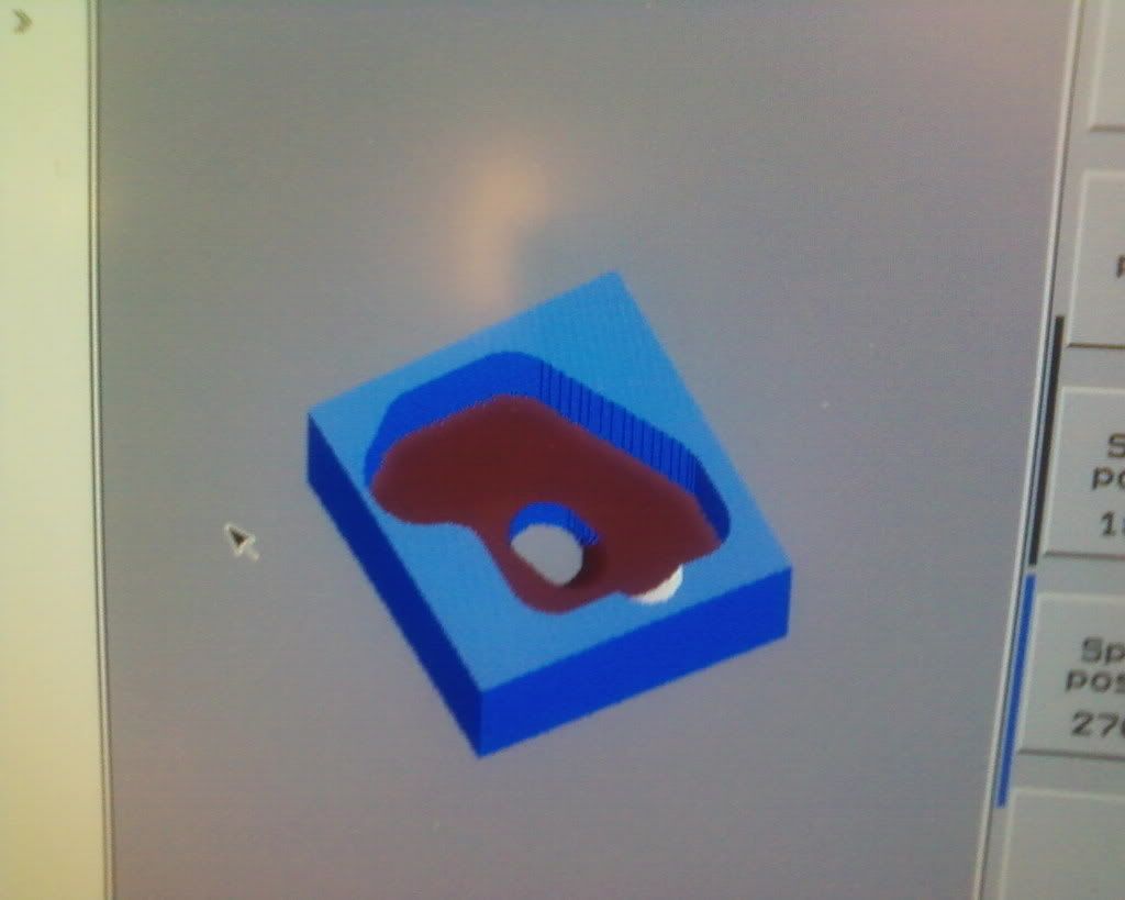
abit of cad on the cnc
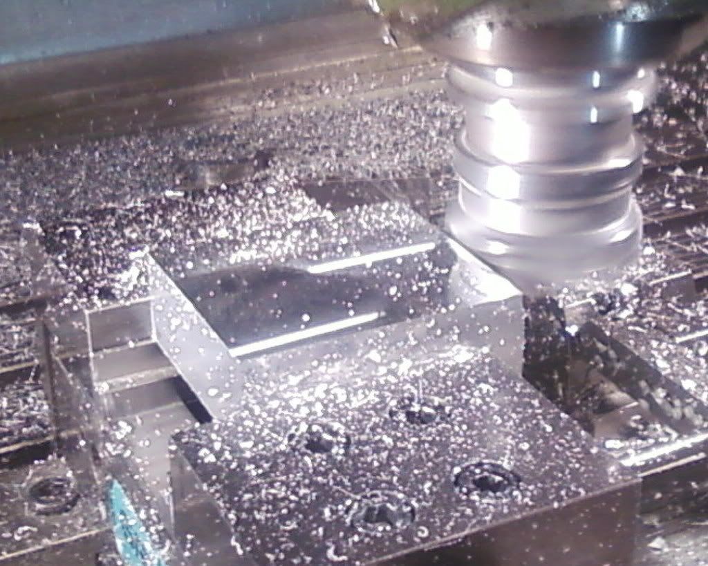
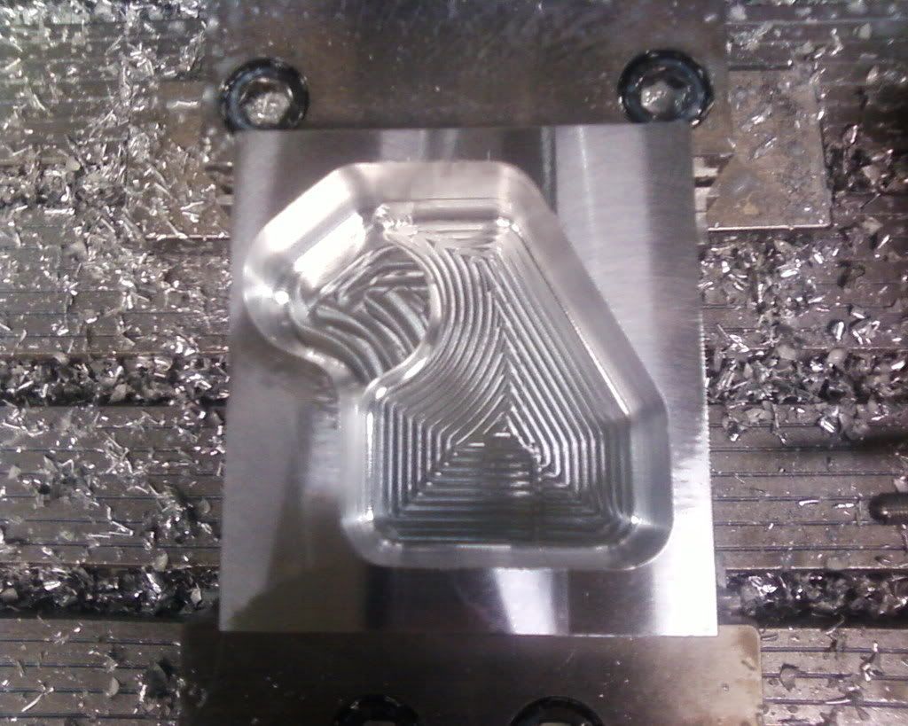
A block off alumec 89 machined into the ruff shape and size of the gearbox
pocket done in the block big enough for the gears bearings and motor mountings etc
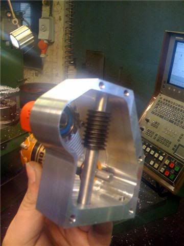
some of the gears fitted. decided to go for a 900:1 reduction via worm gears then steped back up to 450:1 on the final stage of spurr's.. i know worms arnt the most efficient form of transmition, but its only a selfwrighter so shouldnt matter to much
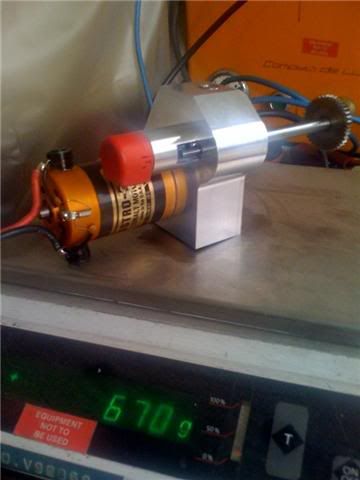
decided to put a potentiometer on the gearbox so it will have some sort of feedback to the H5 driving it (effectivly making the selfwrighter a big servo, the pot is the red thing spaced out from the back plate- the axle for the spur gear 3rd stage pokes out the back of the gearbox and will have nylon gears connecting it to the pot- when i order them from HPC lol this pic also shows the final weight of the gearbox
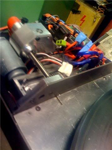
and finaly the gearbox and motor in the robot- tight squeeze but its in there.. just need the spur gears for the pot and the arm finnishing off (already made- it weighs about 50grams, just needs spark eroding)
Just need to re-wire it now- it looks a state in those pics.
- FRA
- Forum
- Robots
- Events
- Media
- What's New?
All times are GMT. The time now is 22:39.

 Reply With Quote
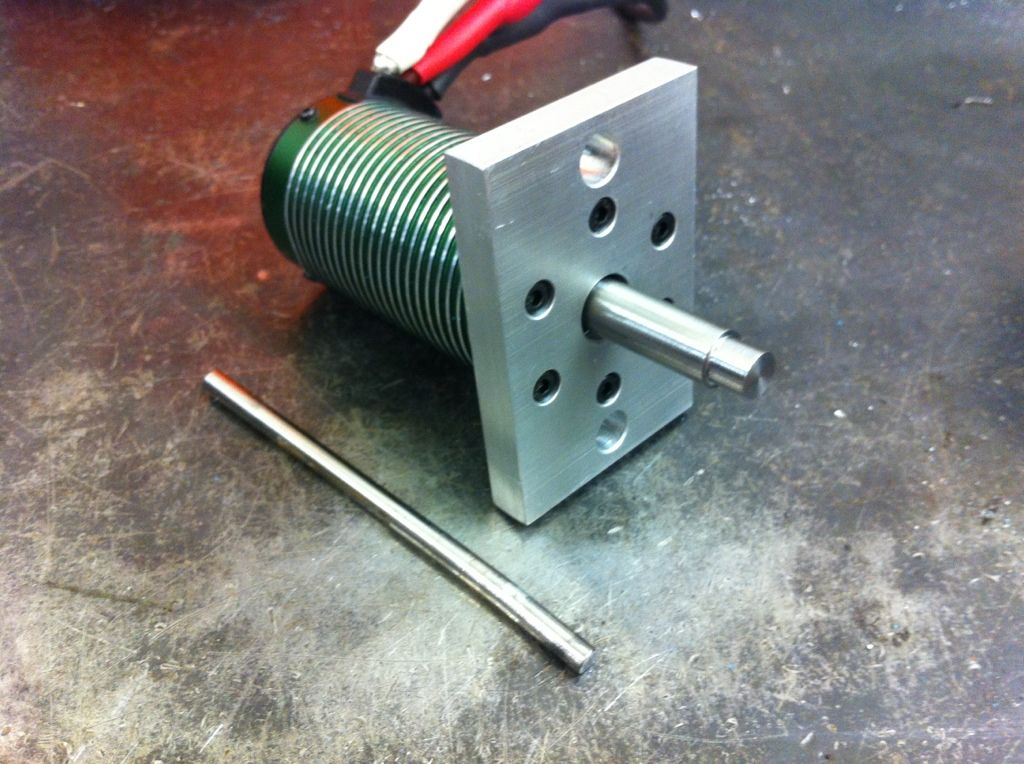


Bookmarks