Hi All,
Not enough people are doing build diaries, so I'm going to make an effort!
I know a lot of you, I have been building things for a good 10 years now.
We built RAPID for RW S9, took a beating, hopefully better things are to come of that robot.
I have been working on a feather for a while, but have finally started cutting metal.
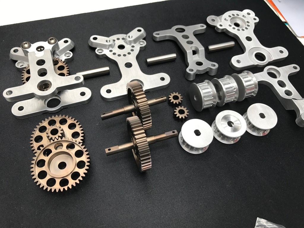
I expect to have the gearboxes ready in the next week or so. I'll start by running through the CAD.
ASTRO is a lazy name, for a silly flipper, as pneumatics are my speciality.
It's hopefully going to be very stable, I've been working to remove the rocking and backflipping from conventional flipper designs.
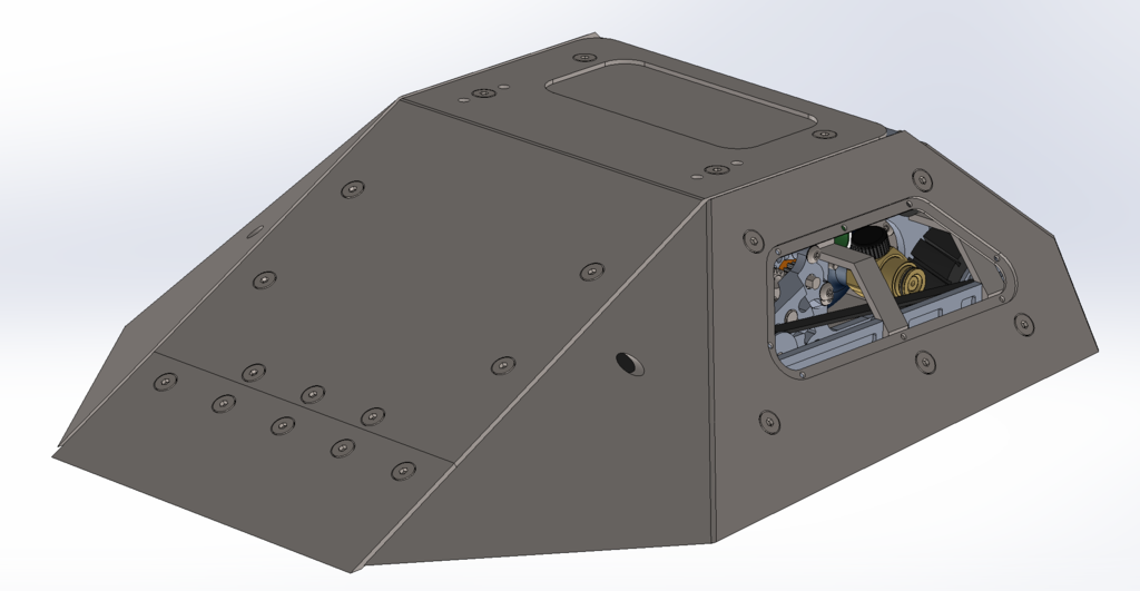
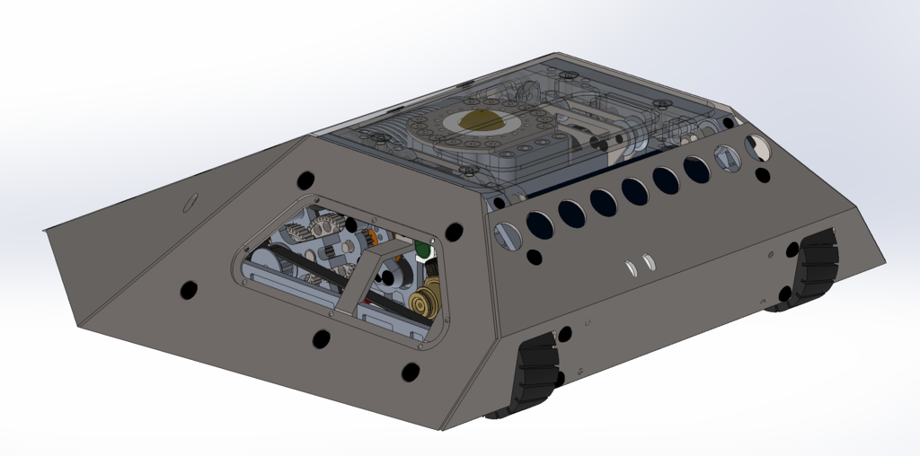
The outer design is pretty common. Shallow edges to stop spinner bites.
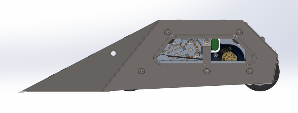
I've brought the front wedge round to try and keep low even when not head on with an opponent.
The flipper rotation point sits quite far forward compared to other robots - this is to move the moment of rotation towards the centre of the wheels and prevent backflips.
I have included replaceable flipper edges, made from hardened tool steel. This is not for armour, but rather so that the edge chips when hit and does not bend - maintaining a sharp edge and not raising the arm at all.
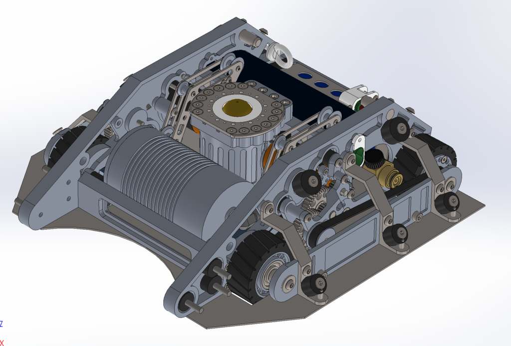
Inside it's a maze of CNC shiny-ness. The robot is quite compact. That core is 345x380mm.
The whole robot sits a max of 120mm off of the ground, including clearance.
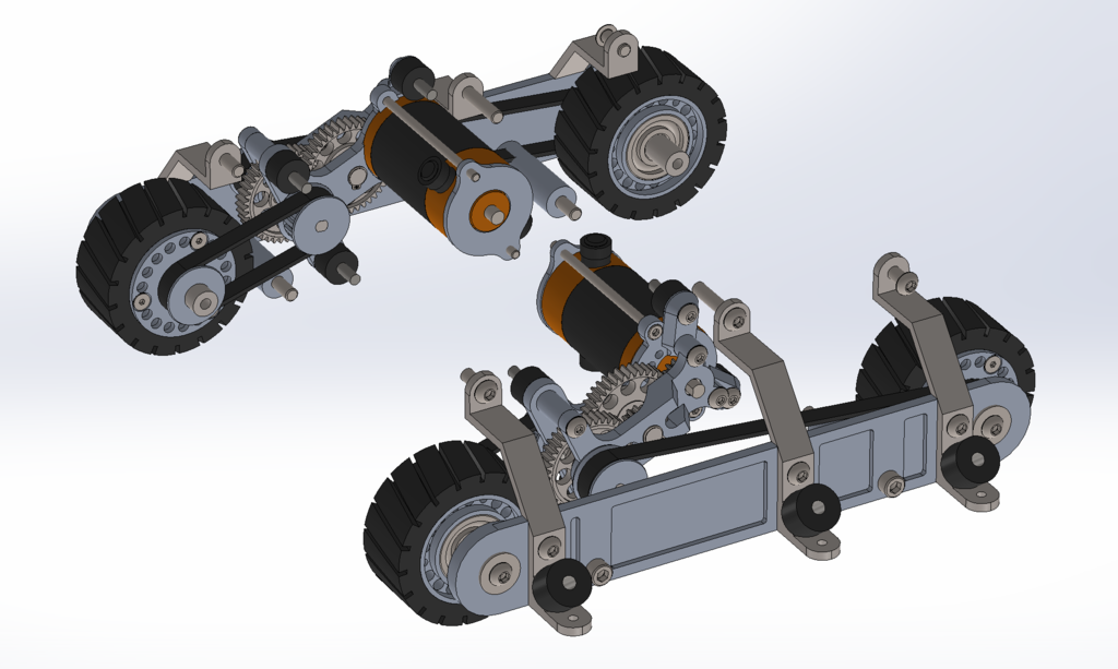
The drive is the first interesting piece.
With inspiration from Dennis, the motors and gearboxes are shock isolated, with belts to a 4wd system.
Those are Astro 640 motors (lazy name) so the power will be pretty high, and the CO2 should help to keep them cool under load.
12:1 on 70mm wheels. The front wheels will be softer to bias the drive further forwards.
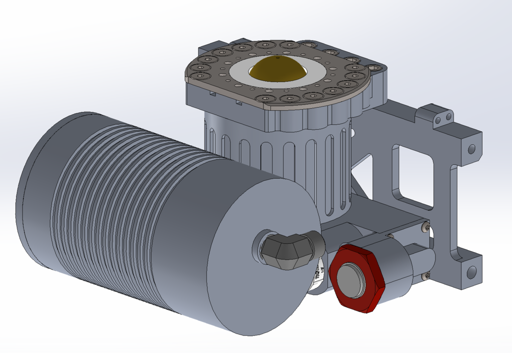
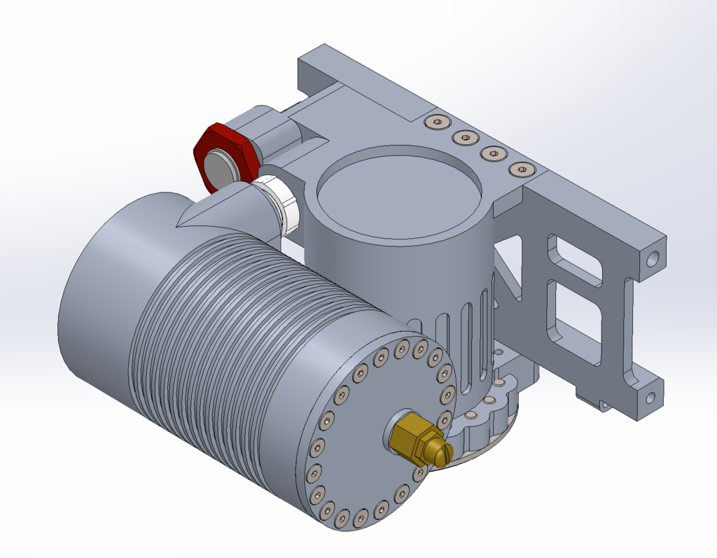
The pneumatic system is fully custom. I had been designing a shuttle piloting valve into the cylinder base, but couldn't reduce the height enough. I have opted for a side porting shuttle valve, actuated by a small hydraulic manifold mount valve I got hold of. I haven't calculated the direct flow rate, but it's a 14mm orefice opening under load from the CO2 pressure, so it should pop nicely.
The fins on the buffer are unlikely to add much temperature advantage to the expanding CO2 but they add strength and reduce weight. I've opted for a brass dome insert in the rod as I noticed a few of the heavies succeeding with this.
Cylinder is 65 di x 60 stroke, and the buffer is 3x volume.
The main cause of backflips in powerful flippers is the rotation point of the flipper, how high it goes under power, and then how high it continues to extend. Usually resulting in a backwards rotation around the wheels.
It's all theory until tested, but looking at a lot of machines and my own experience, with most forwarded mounted bungee, the retract motion is in some cases accelerating the backflip.
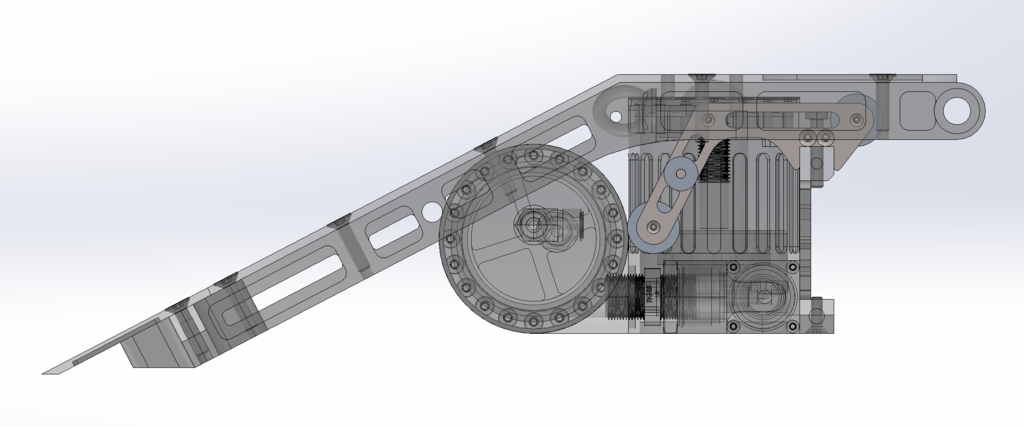
Because of this I wanted to have a vertical bungee retract, close to the cylinder extension.
However doing this does not give much length in the elastic and could result in snapping it, as we did a lot on the heavyweight.
So I'm trying a new contraption. You'll see above the strange pulley hanger - this is allowing a bungee line almost parallel to the cylinder, with a linkage point near to the robot's COG. However the pulleys allow for 4x the length on both sides (incl further routing) and should allow this length to be in use as each pulley will rotate rather than snagging. Let's see!
I'll leave it there. Hopefully I will find time to regularly update on the build.
Josh
- FRA
- Forum
- Robots
- Events
- Media
- What's New?
All times are GMT. The time now is 23:07.



 Reply With Quote

Bookmarks