Register To Comment
Page 4 of 13 FirstFirst ... 23456 ... LastLast
Results 31 to 40 of 125

Thread: [FW] Wedge Spinner in time for Robo Challenge champs!

  1. #31

  2. #32
    If you want to use XT90 connectors, I can send you the STL file for this dual link base:


    Its been working well for the last two years and will save you some valuable time.

  3. #33

  4. #34
    Nah, that part was printed in nylon by Shapeways before I had my own printer and then painted. I have printed similar parts at home and they are really tough with a 100% in-fill. I will send you a PM with the file download location. BTW, here are three good reasons why its better to have two separate fuse links rather than one double:

    * Safer to test the drive motors by themselves.

    * If one fuse blows, you are not throwing out a working fuse as well.

    * Its quite hard to pull out two XT-90 connectors if you need to in a hurry.

    Been there, done that

  5. #35

  6. #36
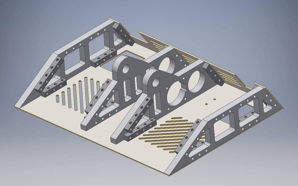
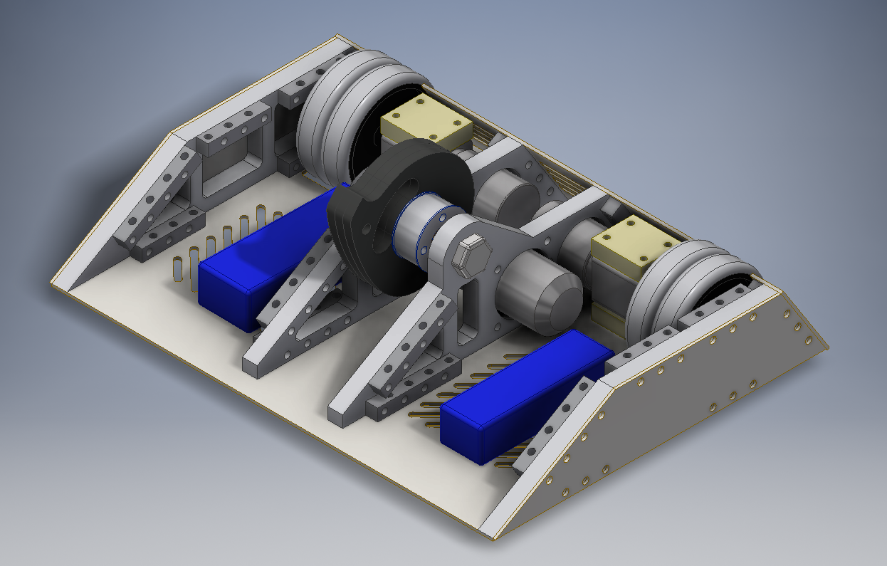
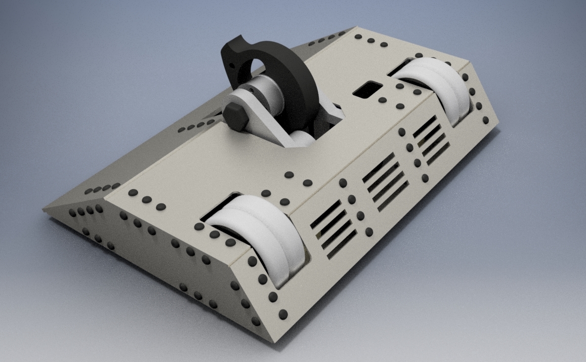
    Looking good! Is there any particular reason for the slots in the back panel? They are taking a lot of strength out of the armour in that area and other vertical spinners will rip them up. The weapon axle looks like it might be a 20mm bolt - that's not really ideal for running a bronze bearing as the bearings need a highly polished surface with accurate dimensions or they wear out fast. Other than that, it looks like a winner

  7. #37

  8. #38
    Given the short build time you have, an M20 bolt makes sense. Bronze bearings are meant to run on precision ground & polished rods but they will run on anything vaguely round with a shorter lifespan. As long as you have some spares and oil the bearings regularly, they should last long enough. If possible, wait until you have the bearings before buying the bolt; take the bearing along and check to see how it fits on the bolt and how smooth the bolt's surface is. I use bronze bearings running on M8 bolts for a lower speed application and they work very well after I polished the bolts a bit.

  9. #39
    Quote Originally Posted by Giles View Post
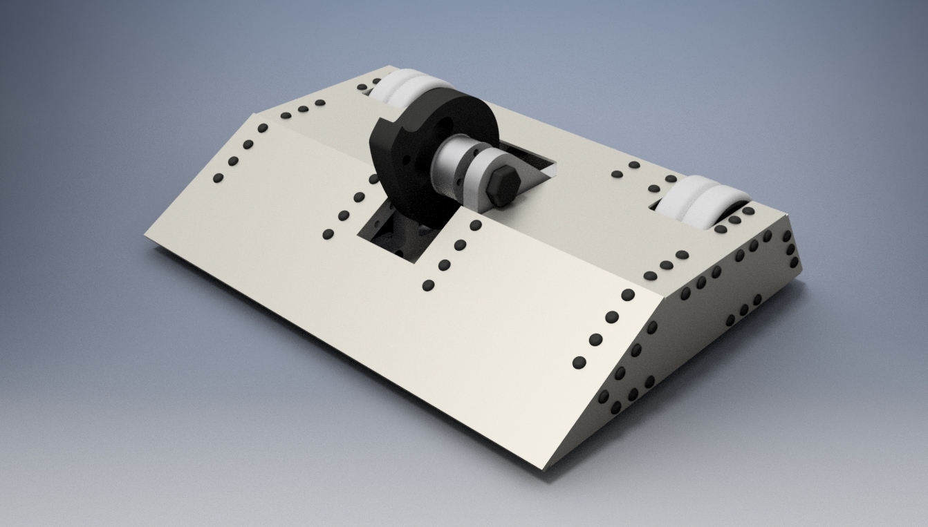
    The only thing I'm not sure about is the placement of the removable link access hole on the top plate, looks very axe-able, but im not sure where else to put it tbh.
    Most people put a cover over the access hole; it seems to be allowed in the rules as long as no tools are needed to open it.

  10. #40
    Quote Originally Posted by Giles View Post
    The only thing I'm not sure about is the placement of the removable link access hole on the top plate, looks very axe-able, but im not sure where else to put it tbh.
    As per the rules it must be a way from any moving parts (wheels tend to be ok so long as its not sharing the same hole or anything stupid) and it must be accessible without tools. Our robots have the rather prominently on the side and top, others bury them under panels inside the robot, these panels can swing shut, be held on with velcro or pinned down with a wing nut. TBH, Link placement is one the things that annoys me the most and tends to be the last thing on my mind when designing a robot, hence Conker 3 and Binky's exposed link positions.

    Looking B-E-A-Utiful btw!

Register To Comment

Tags for this Thread

Posting Permissions

  • You may not post new threads
  • You may not post replies
  • You may not post attachments
  • You may not edit your posts
  •