Register To Comment
Page 38 of 42 FirstFirst ... 283637383940 ... LastLast
Results 371 to 380 of 415

Thread: Team MedBots

  1. #371
    Firstly, nice CAD work, you're clearly comfortable in Solidworks!

    The main question mark from what I see is the strength of the drum mounting. Looks like the shaft is dead which is good, but it seems a bit skinny otherwise. You have what, based on colour, is aluminium plate mounting the drives. Traditionally these would be brought forward and the drum would mount to them, in this case there is a slim (alu?) plate going across the front, which ties into the relatively thin (hardox or otherwise) sides, which then go forwards to support the drum.

    Point is I think a hit from any good horizontal will badly deform the front, either by ripping a side out away from the drum or shunting them both sideways.

    It's hard to strengthen that up without making use of the wheel bulkheads (which would also need thickening depending on grade), but then you get that nobody, mouldy or something they call him, accusing you of making a 720 clone. Number one key to success is don't listen to anything he says, ever.

    It looks like you could save a good bit of weight if you reduced the chassis height? T3's internal height is just 50mm in order to squeeze the most out of the weight limit. Perhaps you can drop the height here so you can put weight back into other areas.

  2. #372
    Max's Avatar
    Member

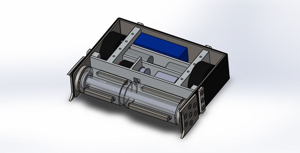
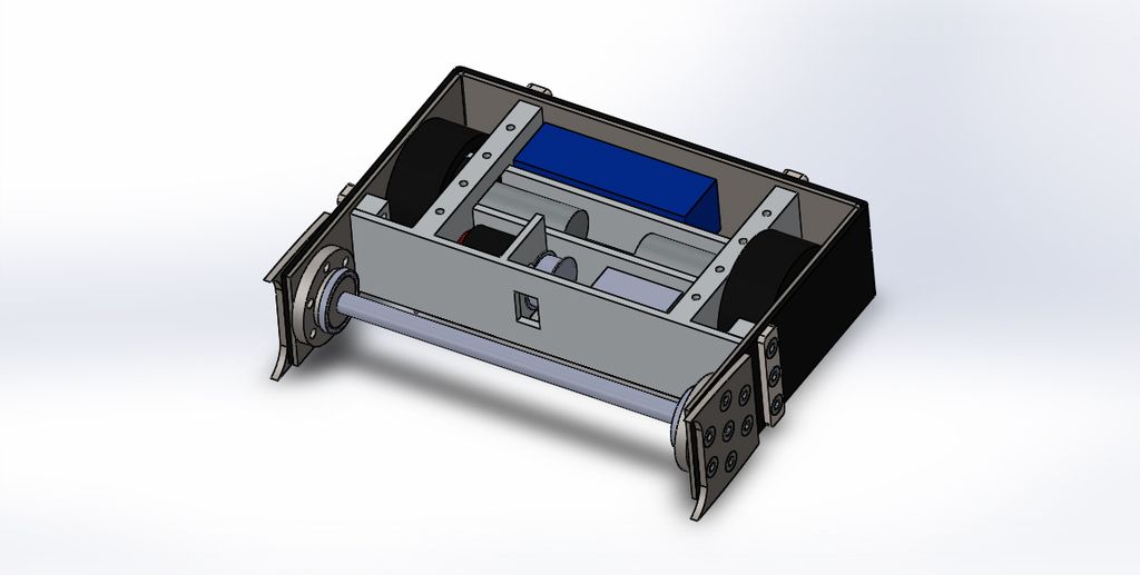
    Yeah I have been concerned about those front plates getting bent and thought about using the wheel bulkheads but as you say then it looks like 520 clone, here are some images without the drum to give you a better idea of how it works:


    There is a large titanium axle at either end 40mm diameter with a 16mm hole though the middle, the drum spins on bearings on these axles then a 16mm rod made of either titanium or aluminium goes all the way through the centre, each end has an M8 tapped hole so a bolt goes from the outside of the hardox armour into these holes, the idea is that this should tie them togather so they are less likely to be pulled apart and also acts as a spacer to stop them being pushed together.

    I have been thinking about making it less tall but it would mean I would have to machine down the flat bar used to make the chassis unless I can get it all the way down to 60mm as I am currently at 3" so it is quite a large step down but may be possible, could mean reducing the drum diameter as well which will mean smaller bearings and so a smaller shaft going through the middle but could save a lot of weight.

  3. #373
    Quote Originally Posted by Max View Post
    Which corners do you mean? You mean the 90 degree folds in the armour at the back?
    Yep, they are very vulnerable to horizontal spinners.

    In Solidworks you can assign materials to different bodies so you don't have to do your calculations manually.

    Asigned Materials C3 01.JPG

    If you right click on a body, materials, edit material, then choose one from the list.

    Asigned Materials C3 02.JPG

    Then you can go to the Evaluate tab and then go to Mass Properties. It will break down all the body masses for you, give you the total and show you the centre of mass.

    The reason I said steer away from GR02's is that their will come a point where there are no more left and suddenly your bot wont work. If something breaks you have no way of replacing it. You are best to design around a part you know is still in production and leave what remains of the GR02's to the machines that already rely on them.

  4. #374
    Max's Avatar
    Member

    Ah ok, I've always just gone into mass properties for each part and manually entered the densities but your way is much easier, I knew there must be a way!

    As for the folds at the back I will have to see what radius I can bend them, not sure exactly how this hydraulic bending machine works so my plan is to start with the hardox and bend it then adjust the CAD to match whatever radius I get before making the rest of the parts to suit. I will ask if they are able to do a sort of chamfer bend with 2 45 degree bends spaced 10-20 mm apart.

    Oh and on the GR02s my main plan is to use the new Ranglebox motors but if they cost an arm and a leg I will have to find an alternative, my hope would be that other people woudo switch to the new motors making some 2nd hand GR02s available. But I was just curious how mario mounted his wheels as I imagine a similar thing could be done with the Ranglebox ones.
    Last edited by Max; 20th June 2015 at 11:44.

  5. #375
    Max, to fit the RC wheels to a GR02 or any other live axle I make a custom adaptor, Hex 17 or 24.

    To ensure the hex staying put on the shaft, I glue it with Loctite 638 and tighten the setscrew.

  6. #376
    I'll have GR02's for sale soonish, send me a PM, we can sort out a price. I will ensure Ellis doesn't lose a sale by purchasing a couple of extra sets of his btw your bulkhead is too thin

  7. #377
    Max's Avatar
    Member

    Quote Originally Posted by Gabe01 View Post
    I'll have GR02's for sale soonish, send me a PM, we can sort out a price. I will ensure Ellis doesn't lose a sale by purchasing a couple of extra sets of his btw your bulkhead is too thin
    Ok, I'll send you a pm.
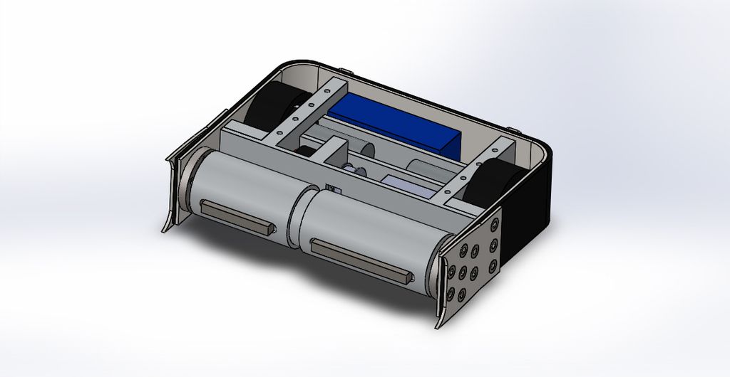
    Latest CAD:


    All Hardox is now 4mm but I have extended those front pieces back to offer more support to the drum. The front thin bulkhead is perhaps a bit thin, I'll see if I can find the weight to thicken it up a bit.

  8. #378
    The front bulkhead doesn't need to be that thick, just as long as it doesn't flex much. I think Dave uses 1.6mm or 2mm ti on 720 without issue. I used 5mm ali on Drumroll and there are two gouges on it from the drum teeth, where it bent outwards towards the weapon after an impact. Was essentially hammering it flat again after every fight.

  9. #379
    Max's Avatar
    Member

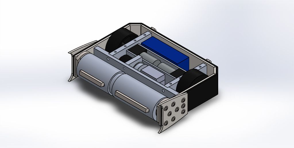
    Thank to Ellis' brilliant suggestion of making it less tall I have made an entirely new CAD model:


    It may well look exactly the same but in fact it is now only 60mm high and by down grading the motors from 775s to 550s I no longer need to have the gearbox sitting inside the wheels so the bulkheads don't have to have a massive 40mm square hole in them for the gearbox. By converting to metric it has also allowed be to slim down the bulkheads to 15mm rather than 3/4" and the fron bulk head has gone up from 1/4" to 10mm. All of this has saved tonnes of weight so all the Hardox has gone back to 6mm and it still had the 4mm HDPE around the outside for added protection though I may thicken this to maybe 10mm. Depending on the wall thickness of the drum there can be just enough weight for a 4mm Hardox top and bottom, though they may need a few holes in them. For now I'll use 6mm polycarbonate and see how the weight is doing.
    First job is to make the outer armour so I will send this off the waterjet cutters soon. One thing I am curious about is what do people think about the fron end? Are the little 'wedgelets' going to get bent up as soon as I hit a joint in the floor?
    Last edited by Max; 22nd June 2015 at 21:51.

  10. #380
    Max's Avatar
    Member

    A CAD animation to show the drum spinning from the side of the robot:


    I'm still concerned about those wedges getting bent too easily by the floor/other robots and am not sure if perhaps they will get in the way of attacking other robots, but also think I will need them to get under other wedges to bring them up into the path of the drum. What do you guys think?

Register To Comment

Posting Permissions

  • You may not post new threads
  • You may not post replies
  • You may not post attachments
  • You may not edit your posts
  •